By Bryce Clerk, Director of Engineering – Acensium
With sources expecting the Bulk Material Handling industry to expand dramatically over the next decade, engineering and upgrading bulk material handling systems efficiently has become a hot topic. Whether engaged in manufacturing, packaging, construction or even mining, upgrades that enhance efficiency keep you competitive but also run the risk of causing unacceptable, costly downtime if there are any unexpected delays or issues in the process. No matter the size or complexity of your engineering project, there are common best practices to optimizing material handling systems with 3D scanning. These hold true despite project size but arguably have the biggest effects on huge projects, where any downtime, delays or mistakes can be devastating.
Before undertaking any project, it’s critical for any project manager or consultant to define precise goals and a tight scope. Understanding the project and its goals thoroughly may seem obvious, but it’s a common point of failure for engineering design and retrofit projects. Ensuring that your 3D scanning team understands the objectives thoroughly allows you to get all the data you need the first time.
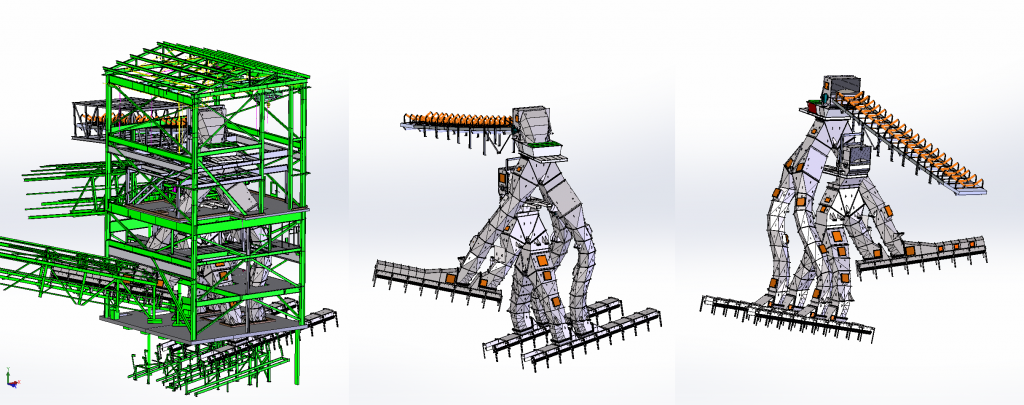
Here’s an example of a huge retrofit project where mistakes causing downtime were unacceptable. A large coal-handling retrofit project where the transfer tower, conveyors and chutework handle thousands of tons per hour (equivalent to thousands of pounds per second) and are usually operating 20+ hours per day in peak season. A legacy system existed where either one of two conveyors load into the same orifice at the top of a transfer tower. The coal would travel through a pair of diverter gates to load either or both of the adjacent conveyors at the bottom floor, either taking coal to the power plant or sending it to a third receiving conveyor, one floor above, that takes coal to a temporary storage area. Whenever the old system had to be shut down due to foreign object(s) entering it, the power plant could be out of business (if coal storage reserves were also low) until the chute was cleaned out. If the plant went down up to $10,000 per minute of revenue could be lost completely.

The key goal of that retrofit project was designing two new, entirely separate systems within the same building such that if one plugged, the other would continue to provide coal to the boilers from the other feeding conveyor. Another crucial objective was making sure that the first of two new systems could be installed while still allowing coal to travel through the old system, with portions of it removed, to eliminate unacceptable downtime. Having a clear understanding of both the main goals and critical requirements around a project is critical for project success.
After client expectations and goals for a project are understood, the design process begins with verifying the dimension and location of every existing, visible instance of steel beam, concrete slab, grating, pipe, conduit and mechanical equipment using 3D laser scanning technology. The 3D scanning equipment creates point clouds, representing the entire area scanned. Typically many scans will be ‘knit’ or ‘stitched’ together to create the full 3D representation of the area and equipment in question. This is a step where it is critical that you have accomplished engineers as part of the scanning team and that objectives are clear. If key areas or equipment is not scanned digital measurements, designs and models will not be able to be properly employed until the missing scans are added.
From the point cloud, which is accurate within millimeters and produced from the 3D scanner, a simplified 3D as-existing model is created. This as-existing model, along with known equipment dynamics and material properties, forms the basis of the new system design. Using 3D CAD design software equipment can be sized and routed to minimize interferences with existing building components while optimizing performance in material handling.
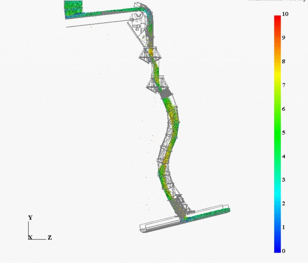
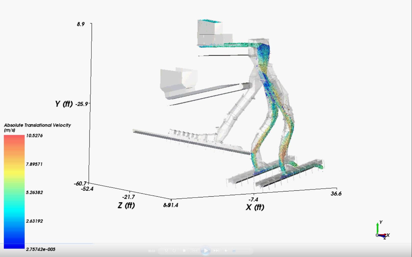
Discrete Element Modeling (DEM), flow-simulation software is one tool used to predict the path of material through material handling systems. Typical performance goals for material handling are achieved through iterative changes to the design as a result of these simulations. These performance goals include things like center-loading of receiving conveyors, reduction of internal chute wear or mitigation of airborne dust. The software models the physics of millions of individual particles based on their material properties. While making iterative changes to the system design, engineers can continually check against the 3D point cloud for interferences with existing building contents.

When the design phase is complete the design for the new material handling system needs to be turned into fabrication drawings for construction. Upon completion of fabrication drawings the new equipment must be fabricated. The dimensional accuracy of the fabrication work should be verified using a 3D laser scanner before it is shipped. This ensures all components are completed as-designed before they arrive at the facility. Following 3D scanned QA approvals of the final fabrication, all equipment is ready to ship for the installation
The precision provided by 3D laser-scanning, modeling and simulation is critical to a project’s success. Chutework often has to dodge major beams or conduit by less than an inch, new conveyors may need to slot in between existing systems, new support steel may need to be added and the placement of new beams, channels, and angles. Complex support designs should be completed by a structural engineer to minimize interferences.

With the existing 3D scans of the facility from the first phase in addition to design models, installation phases and steps can be planned inch by inch. Moving new equipment around a tight facility can be just as challenging as installing new equipment. 3D scanning provides project managers a virtual environment to plan deconstruction/demolition of old equipment and the installation, part-by-part, of new equipment. Planning in 3D reduces unforeseen risk and downtime while enhancing safety, throughout the project.
Once the installation is complete and equipment running as-designed, the final critical step is creating an as-built record. This gives you a baseline for future projects, 3D assets to use engineering upgrades and retrofits for engineering, creating simulations, undertaking safety analysis or building a virtual training environment. Having comprehensive as-built records of all upgrades and changes positions you for success going forward. 3D scanned assets are incredibly valuable and versatile if created and handled according to best practices.
 Bryce Clerk, Director of Engineering of Acensium, LLC
Bryce is the Director of Engineering at Acensium, an industry focused engineering and intellectual services provider with 20 years of experience in power generation. Soon after being hired by Acensium, Bryce successfully executed his first few material handling upgrades for the top-producing power generation plants in the US, relying on 3D Laser-Scanned information as an alternative to traditional methods. After that, he was promoted to Director of Engineering at the age of 24 and has been given responsibility for all of Acenisum’s capital upgrade projects in material handling systems for large power generating companies and iron refining operations. He continues to oversee and design projects with multi-million dollar budgets successfully performing with the help of information captured with 3D Laser Scanning.
Scott Ellyson, CEO of East West Manufacturing, brings decades of global manufacturing and supply chain leadership to the conversation. In this episode, he shares practical insights on scaling operations, navigating complexity, and building resilient manufacturing networks in an increasingly connected world.