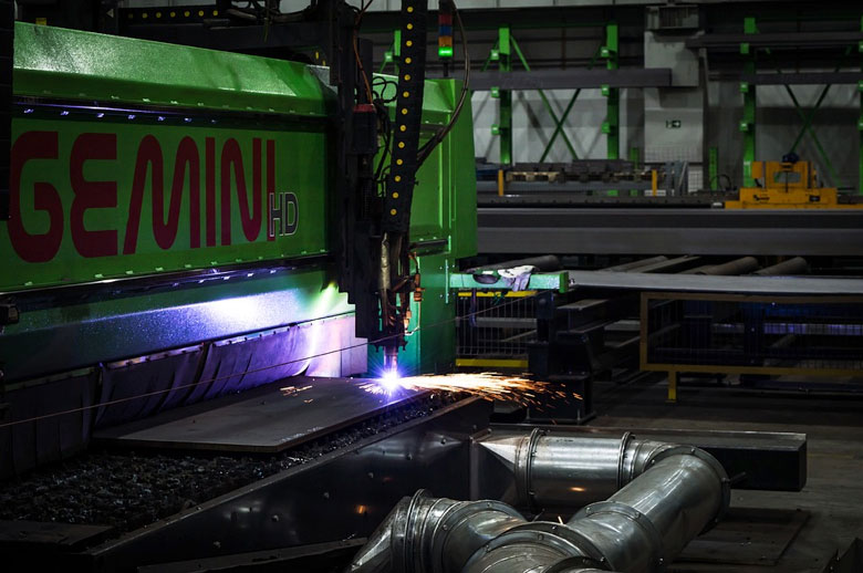
Design for Manufacturing (DFM) guidelines, used in all manufacturing processes, ensure a design is reproduced accurately.
October 24, 2019
Sheet metal fabrication involves cutting, bending, and perforating a piece of metal. These manufacturing processes are surprisingly accurate, but they leave room for errors that may compromise the final design. Design for Manufacturing (DFM) guidelines are used to ensure that a design can be accurately reproduced by the available technology. DFM is used for all manufacturing processes, including 3D printing and injection molding, but the guidelines are particularly important for metal fabrication.

Basic DFM guidelines for sheet metal
Most DFM guidelines are intended to keep the sheet metal from warping, tearing, or cracking. This can happen either during the manufacturing process or when the product is in use. In general, leave enough space between design features so that slight variations in the metal will not impact the final structure.
- Hole diameters: Hole diameters should be greater than the thickness of the sheet metal. This ensures efficient punching and smooth edges.
- Hole spacing: Spacing between holes or between a hole and a boundary should be at least twice the sheet thickness. If the hole is near a bend, make sure the hole is outside of the bend radius.
- Bend relief: Bend reliefs are necessary to prevent the sheet metal from tearing either during the manufacturing process or after stress is put on the object. Reliefs should be added whenever there is material on either side of the bend.
- Support features: Beads, flanges, collars, and other similar features are used to support the object after manufacturing. Without them, the metal can collapse or bend back into its original shape. Failure to add these features to the initial design will actually increase manufacturing times and production costs.
- Grain structure: Like most materials, sheet metal has a grain. If lugs or tabs are made parallel to this grain, the metal may crack when later pressure is applied.
- Clearance: Leaving a wider engineer clearance between a punch and the die results in a smoother process and lower manufacturing costs. Consider making tolerances looser to facilitate easier production.
Making DFM a part of the engineering process
Designs that follow DFM guidelines are as streamlined and easy to produce as possible. This can be accomplished by reducing the part count, making sure that the product is easy to assemble, and checking that the design does not stress the limits of current manufacturing capabilities. These guidelines result in lower production costs and designs that are easy to recreate for future applications.
- Consolidated parts: Every object should be designed with the lowest possible part count. Parts should be consolidated if they can be made from the same material, don’t need to move relative to each other, and don’t require special insulation or maintenance.
- Easy assembly: Assembly is a particularly important consideration when designing for sheet metal parts. Create intuitive designs that naturally slide into place in the proper orientation.
- Simple manufacturing: A good design shouldn’t stress the limits of the available manufacturing capabilities. For modern sheet metal fabrication, avoid thin walls or deep pockets, provide mounting surfaces for clamps, and simplify features to reduce production times.
