This paper will focus on the differences in motion technology, and the advantages and disadvantages of the various systems available today.
Michael R. Fredbloom, Roberts Sinto Corporation, Grand Ledge, Michigan
As the foundry industry strives to improve quality, reliability and maintainability along with reducing their carbon footprint, many companies are starting to explore replacing fluid power (hydraulic, pneumatic or a combination of both) driven systems with electrical actuation (servo-cylinder, electric rack-and-pinion drives.) Electrical actuator systems typically offer lower overall noise and reduction in power requirements, eliminate the need for hazardous hydraulic fluids and offer a consistent form of locomotion that can be difficult to achieve using fluid power. This paper will focus on the differences in motion technology, and the advantages and disadvantages of the various systems available today.
There are many variables to consider when it comes to molding handling systems. Type of molding machine used within the system, speed of the mold machine or molds per hour, size of mold, pouring area, casting cooling time, size of the pouring line, etc.
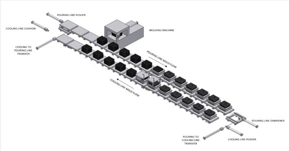
Mold handling line speed and load determine the forces needed to control the molding lines. As the speed and mass of a mold handling lines increase, so do the forces needed to control the molding line both accelerating and decelerating. Pushing devices are needed to accelerate the molding lines, and damping devices are needed to decelerate to molding lines. Refer to Figure 1.
These pushing and dampening devices have typically been a fluid power cylinder or motor driven rack and pinion. Electric servo cylinders are starting to become a more popular solution for pushers and dampeners and offer several advantages over both pneumatic and hydraulic.

Figure 1. A simple two line, pouring and cooling, molding system showing pushers and dampening cylinders.
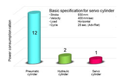
In general, we can see that for one watt consumed by a servo cylinder, a hydraulic cylinder and system would consume approximately two watts, and a pneumatic cylinder and system would consume approximately twelve watts. (Figure 2. 1)
This reduced energy consumption would have a significant impact on annual energy savings. Sintokogio studies show that with molding lines using forty-four servo cylinders, annual savings of up to 3.4 million Japanese yen (approximately $32,000) per year are possible, compared to similarly sized hydraulic cylinders.

Figure 2. Power consumption ratio per cylinder.
Further savings may be achieved when choosing electric over hydraulics in the form of reduced maintenance costs. Yearly mechanical overhead of cylinders would remain the same for servo cylinders and hydraulic cylinders. Yearly overall cost of hydraulic power unit pumps, filters, fluid and other consumables may reduce yearly maintenance costs by 60%.
A reduction of energy also results in a reduction in CO2 and noise. In 2018, the U.S. Energy Information Administration reported “the total U.S. electricity generation by electric power industry of 4.17 trillion kilowatt hours from all energy sources resulted in the emissions of 1.87 billion metric tons – 2.06 billion short tons – of carbon dioxide (CO2).” This equals about 0.99 pounds (0.449kg) of CO2 emissions per kWh.2
Using the previous example, a hydraulically driven molding line with forty-four cylinders would consume approximately 0.5MkWh yearly, resulting in nearly 12,300kg (27,120pounds) of CO2 emissions yearly.
The same example using electric servo cylinders would annually consume approximately 0.27MkWh, resulting in nearly 6,700kg (14,770 pounds) of CO2 emissions yearly.
It is understood that nearly 63% of U.S. electricity is produced by fossil fuel power plants.3
The resulting reduction in CO2 emissions using servo cylinders ranges between 3,500kg (7,720 pounds) and 5,600kg (12,350 pounds) of CO2 yearly.
Within the working environment, OSHA’s 90dBA permissible exposure limit for workers may require hydraulic power units with noise producing pumps to be housed in their own room or a different floor due to their noise generation. Servo drive packages and variable frequency drives are housed within enclosures, greatly reducing the noise generated by a molding system.
Electric actuators eliminate the possibility of hydraulic oil leaks and the need to clean up after them, improving system maintainability.
Colder temperatures and morning start-ups can lead to a higher hydraulic fluid viscosity. Mold handling systems using simple hydraulic systems using basic directional valves to control the mold handling motions will move slower than a system that is up to temperature.
Mold handling systems with more complex hydraulic systems with proportional valves and position feedback can compensate for colder temperatures somewhat through complex programming algorithms.
Fluid heating circuits could be added to the hydraulic system. A simple pressure relief valve set to a very low pressure is sometimes used to raise temperature of hydraulic fluids to operating temperature, increasing the energy consumed without producing castings.
Once the hydraulic fluid is up to temperature and the mold handling system is operating at a steady state condition, now preventing the fluid from overheating is a concern. These fluid operating temperature extremes are not unusual conditions in some areas of the country.
Hydraulic heat exchanges are added to the system to prevent hydraulic fluids from overheating. More energy is consumed pumping hydraulic fluid to cooling towers, continuous recirculation pumps and cooling fans.
Over time, with this cycle of cold start up and cooling of the hydraulic fluid once steady state operation is achieved, adjustments will need to be made to continue smooth operations. Simple mold handling systems with directional valves will require maintenance personnel to adjust valve control valves mounted at the actuator or at the solenoid valve.
With a more complex system using proportional valves, trained technicians may be able to adjust the acceleration and deceleration of the molding line using the mold handling system operator interface panels.
Electrical servo cylinders and rack-and-pinion are not affected by the fluctuations in temperature as hydraulics can be. Similar to the more complex hydraulic molding line, any adjustment needed can be made by trained technicians using the mold handling lines operator interface panels.
Hydraulic systems with power units consisting of pumps, fluid reservoirs, filtration systems and cooling circuits can be quite sizeable. Including with that the hydraulic manifolds, circuits and fluid conductors (piping) to control the size, the footprint of a complete hydraulic system is quite sizeable.
Similarly, pneumatically driven systems require a large compressor and similar manifolds, circuits and piping to control a pneumatically driven system.
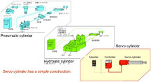
By comparison an electrically driven footprint is much smaller. A motor drive and controller are typically housed within an enclosure close to the actuator they are controlling. The total of components needed for pneumatic and hydraulic systems is much greater than the components needed for a servo cylinder application. (Figure 3.)
Rigid piping of a fluid power systems give way to cable treys and lay-in-plug in cables, making setup, tear-down and installation less time consuming.

Figure 3. A comparison of components needed for one actuator.
When choosing between a fluid power or electric mold line, electric will consume less energy, producing less CO2, and an electric system will produce less noise, making it cleaner for the environment both externally and internally. Mold handle line operation is stable regardless of temperature conditions, which affect hydraulic fluids. The overall footprint of an electric servo cylinder system is less than both hydraulic and pneumatic, freeing up valuable floor space.
REFERENCES
Scott Ellyson, CEO of East West Manufacturing, brings decades of global manufacturing and supply chain leadership to the conversation. In this episode, he shares practical insights on scaling operations, navigating complexity, and building resilient manufacturing networks in an increasingly connected world.